Orbital Implants in the Management of Orbital Fractures
All content on Eyewiki is protected by copyright law and the Terms of Service. This content may not be reproduced, copied, or put into any artificial intelligence program, including large language and generative AI models, without permission from the Academy.
Orbital Implants in the Management of Orbital Fractures
Introduction
An implant is any material inserted into the body cavity to replace, support or enhance a missing biological structure.
Background
Orbital and orbitofacial fractures are common fractures of the midfacial skeleton with structural, functional and aesthetic consequences. The goals of orbital reconstruction in trauma is to atraumatically reduce orbital soft tissue contents thereby restoring and supporting the position of the globe and orbital soft tissues, avoiding post-traumatic enophthalmos and to restore normal function and esthetics.[1] Numerous techniques and materials are available for the repair of these fractures.[2] [3] [4] [5] [6] While small defects my heal partially or completely, larger defects, especially those at risk of producing enophthalmos, diplopia and hypoglobus often require an alloplastic implant material of sufficient strength with optimal position and contour to support the orbital contents and restore the premorbid structural anatomy of the orbit.[1]
Classification of orbital & orbitofacial fractures
A Practical Classification of orbital fractures can be into pure/simple orbital fractures alone or complex orbitofacial fractures. Pure/simple orbital fractures are fractures that only involve the internal orbital walls without displacement of the orbital rims. They can be broadly classified into linear fractures, blow out and the less frequent blow in fractures. Complex orbitofacial fractures are orbital fractures that involve rest of the craniofacial skeleton and may be classified into zygomatico-maxillary complex fractures (involving the lateral wall and lateral orbital floor), naso-orbito-ethmoidal fractures (involving the medial wall and lacrimal drainage system), orbitofacial fractures (Le Fort II {medial wall and floor} & Le Fort III fractures {medial wall and lateral wall fractures}), cranio-orbito-facial and panfacial fractures (upper, midface and lower facial skeleton).[7] It should be remembered that pure orbital fractures (blow out or blow in) are only a small component of all orbital fractures. A Practical Classification of Orbital and Orbitofacial fractures of relevance to the Ophthalmologist and Oculoplastic surgeon is shown in Table 1 below.
Table 1: Practical Classification of Orbital & Orbitofacial Fractures. with permission from ' Orbital fractures: Principles, Concepts & Management' Ed by Sundar G.
| Pure or Simple Orbital Fractures |
|---|
| Linear fractures |
Blow out fractures
|
Blow in fractures
|
| Complex Orbital/Orbitofacial Fractures |
|---|
| Zygomatico-maxillary complex (ZMC) fractures (commonly lateral wall + floor) |
| Naso-orbito-ethmoidal (NOE) fractures (commonly medial wall) (Types I, II and III) |
| Cranio-orbital fractures (commonly orbital roof involving the skull base) |
Orbito-facial fractures.
|
| Panfacial fractures (upper face, midface, and lower facial fractures) |
Indications, threshold and timing of fracture repair
All significantly displaced orbital fractures (orbital rims and /or walls) at risk of developing post-traumatic deformity including enophthalmos, residual diplopia with appropriate risk stratification are indications for orbital fracture repair. The exceptions are linear or trapdoor fractures with minimal displacement but without entrapment of the medial or inferior rectus – intermuscular septum complex typically seen in children and young adults. In an evidence-based protocol published by Burnstine[8] on orbital blow out fractures, indications for immediate surgery included entrapment and large fractures where latent enophthalmos was imminent. Observation is preferable for small fractures with minimal diplopia and intact extraocular movements. Subsequent surgical intervention is performed in those observational cases when diplopia persists or enophthalmos becomes clinically apparent following resolution of edema.[8] Other indications for surgery include trismus, increased mid-face width or malar flattening from a zygomatico-maxillary (ZMC) fracture, or telecanthus and facial deformity from a naso-orbito-ethmoid (NOE) fracture in a patient concerned about the deformities.
Principles of orbital & orbitofacial fractures reconstruction
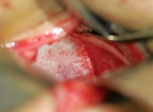
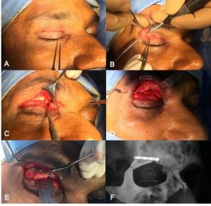
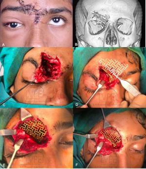
After stabilizing life and vision, assessing the indication for orbital fracture repair and fitness of the patient, orbital fractures are exposed by various incisions, followed by atraumatic reduction of orbital soft tissue contents with preservation of the various neurovascular bundles and other vital structures, fixation of displaced orbital rims along with the facial buttresses, and finally reconstruction of one or more orbital walls as indicated. Intraoperative and postoperative verification of accurate reduction and placement of orbital implants are essential components of the surgery performed. Typically, the rims are repaired using permanent rigid fixation (eg titanium miniplates) (Figure 1) (beyond the scope of this review) and the orbital walls are reconstructed using implants placed on bony ledges or anchored to the orbital rims (Figure 2).
Ideal implant
Some ideal characteristics of orbital implants include
- Stability and fixation: Strong enough to support orbital contents, retain shape once manipulated, remain stable, and when necessary to be able to be fixated to stable bony landmarks.
- Contour and handling: Orbital implants should be easy to shape and fit the orbital defects preserving regional anatomy. They should not have sharp edges that impinge or tether soft tissues, have a smooth surface that adequately bridge bony defects along one or more walls.
- Biologic behaviour: They should be inert (non-allergenic and non-carcinogenic) with low risk of infection, migration, extrusion or inducing foreign body reaction. They should also biointegrate easily with minimal resorption for permanent implants and resorb at an acceptable pace for bioresorbable implants. Exceptionally, when implant removal is indicated, they should be amenable to dissection for implant removal during secondary reconstruction.
- Donor site issues: They should not increase surgical complication rate, with minimal harvesting time and donor site morbidity.
- Cost & availability: Affordable and readily available to patients/surgeons.
Implant materials
There are several implant materials used in orbital reconstruction. Based on various characteristics orbital implants may thus be classified into
- Source: Autologous, Allogeneic and alloplastic[1] [2] [3] [4] [5] [6]
- Based on material: Permanent or bioresorbable
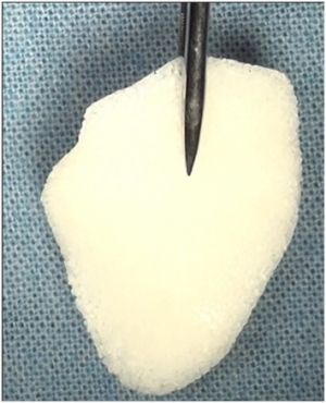
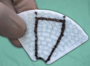
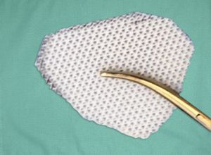
- Based on porosity: Porous (titanium implants, porous polyethylene(Medpor®), or non-porous (silastic, porous polyethylene (with barrier film)
- Based on type: Stock implant, modified stock implant or customized (patient specific) implant
Autologous implants
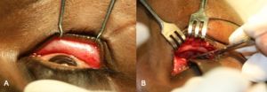
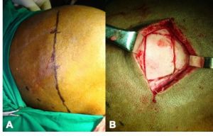
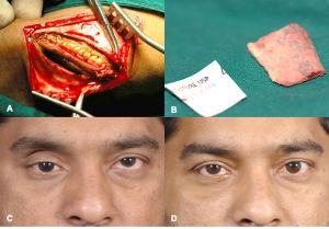
These implants include bone, cartilage, fascia and periosteum. Autologous bone can be harvested from the iliac crest (Figure 3), calvarium (figure 4), ribs or the mandible. Autologous cartilage can be harvested from nasal septum, concha, auricle or ribs. Temporalis fascia or tensor fascia lata and autogenous periosteum have also been used as orbital implants. In general, autologous implants are less preferable due to potential donor site morbidity, contour or structural support issues.
Allogenic implants
These implants include lyophilized dura mater, demineralized human bone, lyophilized cartilage, irradiated fascia lata and bovine bone but seldom used.
Alloplastic implants
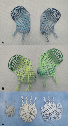
These are the implants of choice in most orbtial fracture defects. They may be classified into Permanent (synthetic polymers, titanium, etc) or Bioresorbable Implants or as Single material (polylactides, polycaprolactones, porous polyethylene, titanium) implants or combination material (porous polyethylen-titanium) implants .[9] or based on their shape into sheet implants (eg Silicone, poroous polyethylene, titanium mesh) or anatomic implants (MatrixORBITAL preformed implants , or Patietn Specific implants (PSIs). Bioresorbable alloplastic materials include polylactic/polyglycolic acid copolymers (RapidSorb®, Inion(R), polydioxanone (PDS), polyglactin 910 polydioxanone, Polycaprolactone (Osteopore®), etc.[10] [11] In general, fenestrated implants have the advantage of minimizing orbital compartment syndrome and allow tissue ingrowth until integration or complete bioresortpion..
In general, rim fractures are fixated with permanent (Titanium) miniplates with screw fixation (Figure 5). Small to medium sized wall defects may be reconstructed with sheet implants. Large and complex (multiple wall) defects may be reconstructed with permanent and contoured implants, although prebent bioresorbable implants have also been described.[7]
In a systematic review from 2012 of 3475 pure orbital floor reconstructions from 48 studies, autologous calvarial bone grafts, porous polyethylene and PDS were most widely used.[12] Increased infection rates were reported with polyglactin 910/PDS composites and silastic rubber. Ocular motility was reduced most with lyophilized dura and PDS. Preoperative and postoperative rates for diplopia and enophthalmos varied among the materials.[12] Titanium orbital meshes have been the standard of care in the management of large and complex orbital fractures since the past decade. The orbital reconstruction with titanium meshes evidences good outcome in single wall and multiple wall fractures.[13] However, the risk of malposition increases massively with fracture size.[14] Patients with large orbital defects needing surgical treatment are at risk of implant malposition. Schlittler et al[14] postulate that in large, two-wall fractures, primary treatment with a patient specific titanium implant has to be considered. Prebending anatomic prefabricated implants based on the angle of inferomedial orbital strut (AIOS) has also been described.[13]
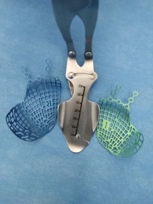
Patient specific implants: These are 3D printed implants that are specifically designed for the individual patient based on the mirrored contralateral normal orbit or predetermined 3D reconstruction using the DICOM data from preoperative CT scans. An alternative is to pre-contour titanium plates based on (Figure 6) 3D stereolithographic (STL) models which can be printed based on mirroring the non-fractured orbit of the patient using a medical imaging software.[13]
Bioresorbable implants
Bioresorbable implants offer a useful alternative in the reconstruction of small to medium defects in simple or complex orbitocranial deformities. They have the advantages of alloplastic and autologous implants, that is,
- Complete disappearance following bone healing, eg Polylactides, Polycaprolactones
- provide mechanical integrity while the polymer resorbs and
- avoiding donor-site morbidity.[11]
Young et al[11] reported late postoperative imaging at 15-24 months following fracture repair and demonstrated complete resorption of implants and features of neobone formation in all of the 98 patients operated for fracture repair with a bioresorbable implant.
Advantages and Disadvantages
A wide variety of implants and biomaterials are available for orbital reconstruction. Some common implants, their advantages and disadvantages, are mentioned in Table 3. While other permanent implants including silicone, nylon (Suprafoil®), and other materials have been used, they are no longer recommended owing to their various limitations.
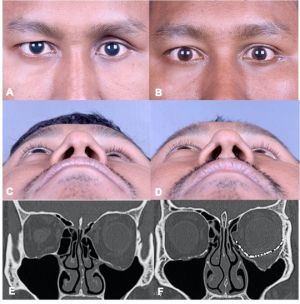
Table 3: Advantages and disadvantages of implants and biomaterials used for orbital reconstruction (Table 3 and figures 9, 10 and 11 reprinted with permission from Book chapter on Orbital fractures: a conceptual approach by Gangadhara Sundar, Manual of Oculoplasty, India, Jaypee digital, 2019)
| Permanent Implants | Advantages | Disadvantages |
|---|---|---|
| Titanium
(Figure 7) |
|
|
| Porous polypropylene
(figure 8) |
|
|
| Composite (hybrid) implants (porous polypropylene with titanium
Titan®, Synpor® (Figure 9) |
|
|
| Poly L/DL Lactide 85:15 (Rapidsorb)
(Figure 10) |
|
|
| Poly L/DL Lactide 70:30
(Polymax) |
|
|
| Polycaprolactone (PCL, Osteomesh®)
(Figure 11) |
|
|
| Polydioxanone (PDS) |
|
|
| Bone graft |
|
|
Surgical technique
The incisions used for managing orbital fractures are decided based on the type of fracture. Minimally invasive approaches are preferred where possible to access the fracture the site, reduce the orbital contents, identify bony landmarks and place/anchor the implant with intraoperative verification. In general, orbital floor and medial wall fractures may be approached with transconjunctival incisions. Zygomaticomaxillary (ZMC) fractures may be approached with the above incision along with an upper blepharoplasty incision, an oral supragingival incision and/or coronal incision based on the complexity/duration since fracture. Naso-orbito-ethmoid fractures are usually accessed through a coronal incision.[9] Goals of orbital reconstruction include atraumatic release of herniated or prolapsed orbital soft tissue, complete orbital soft tissue reduction, accurate and anatomic reconstruction of the orbital wall(s), restoration of premorbid orbital volume, avoidance of damage to vital structures, for example, extraocular muscles, intermuscular septum, motor and optic nerves, thereby preserving vision and minimizing or preventing diplopia and to avoid both short and long-term implant related complications.[9]
Use of technology for improved outcomes
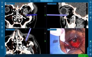
The use of intra-operative image guidance(navigation surgery)[15] (figure 12) and prebending implants on 3D printed skull models[13] for implant customisation can help improve surgical outcomes.
Postoperative imaging of orbital implants
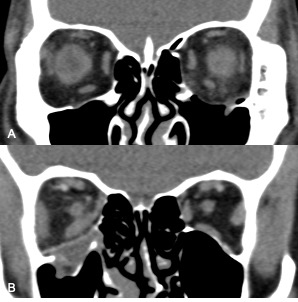
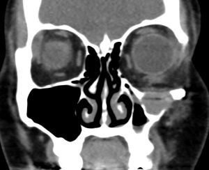
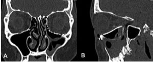
Imaging of orbital fractures is indicated postoperatively to ensure accurate placement of orbital implants, occasionally when postoperative complications arise and when revision surgery is planned. This not only helps identify positioning of implants, but also assess orbital volume and soft tissue consequences and also guide additional surgery when indicated. While metallic implants are radioopaque and easily visible (figure 13 and 14) and easily visualized on bone and soft tissue windows, porous polyethylene implants and bioresorbable implants are more radiolucent and better visualized in soft tissue windows (Figure 15). Examples of suboptimal and good reconstruction with implant characteristics are shown below (Figure 16 and 17).
Complications
Complications from orbital surgery include infection of implanted material, implant migration, epiphora, worsening diplopia, lower eyelid retraction, blindness and residual enophthalmos.[15][16] [17] [18] [19] [20] Visual loss is a rare but serious complication following repair of orbital fractures.[21] [22][23] The mechanism may be optic neuropathy from traumatic dissection, retrobulbar hemorrhage or injury to the optic nerve from a misplaced orbital implant.
References
- ↑ 1.0 1.1 1.2 Dubois L, Steenen SA, Gooris PJ, Bos RR, Becking AG. Controversies in orbital reconstruction-III. Biomaterials for orbital reconstruction: a review with clinical recommendations. Int J Oral Maxillofac Surg. 2016 Jan;45(1):41-50.
- ↑ 2.0 2.1 Mok D, Lessard L, Cordoba C, Harris PG, Nikolis A. A review of materials currently used in orbital floor reconstruction. Can J Plast Surg. 2004 Fall;12(3):134-40.
- ↑ 3.0 3.1 Sundar G. Classification of orbital & orbitofacial fractures.In: Sundar G (Ed).Orbital Fractures – Principles, Concepts& Management. USA: Imaging Science Today; 2018. ISBN:978-0-9977819-2-2.
- ↑ 4.0 4.1 Dubois L, Steenen SA, Gooris PJ, Bos RR, Becking AG. Controversies in orbital reconstruction-III. Biomaterials for orbital reconstruction: a review with clinical recommendations. Int J Oral Maxillofac Surg. 2016 Jan;45(1):41-50.
- ↑ 5.0 5.1 Dubois L, Steenen SA, Gooris PJ, Mourits MP, Becking AG. Controversies in orbital reconstruction--II. Timing of post-traumatic orbital reconstruction: a systematic review. Int J Oral Maxillofac Surg. 2015 Apr;44(4):433-40.
- ↑ 6.0 6.1 Dubois L, Steenen SA, Gooris PJ, Mourits MP, Becking AG. Controversies in orbital reconstruction--I. Defect-driven orbital reconstruction: a systematic review. Int J Oral Maxillofac Surg. 2015 Mar;44(3):308-15.
- ↑ 7.0 7.1 Book chapter on Orbital fractures: a conceptual approach by Gangadhara Sundar, Manual of Oculoplasty, India, Jaypee digital, 2019.
- ↑ 8.0 8.1 Burnstine MA. Clinical recommendations for repair of isolated orbital floor fractures: an evidence-based analysis. Ophthalmolgy 2002;109:1207–1210, discussion 1210–1211, quiz 1212–1213.
- ↑ 9.0 9.1 9.2 Seen S, Young S, Lang SS, Lim TC, Amrith S, Sundar G. Orbital Implants in Orbital Fracture Reconstruction: A Ten-Year Series. Craniomaxillofac Trauma Reconstr. 2021;14:56-63.
- ↑ Seen S, Young SM, Teo SJ, Lang SS, Amrith S, Lim TC, Sundar G. Permanent Versus Bioresorbable Implants in Orbital Floor Blowout Fractures. Ophthalmic Plast Reconstr Surg. 2018;34:536-543.
- ↑ 11.0 11.1 11.2 Young SM, Sundar G, Lim TC, Lang SS, Thomas G, Amrith S. Use of bioresorbable implants for orbital fracture reconstruction. Br J Ophthalmol. 2017;101:1080-1085.
- ↑ 12.0 12.1 Avashia YJ, Sastry A, Fan KL, Mir HS, Thaller SR. Materials used for reconstruction after orbital floor fracture. J Craniofac Surg. 2012;23:1991-7.
- ↑ 13.0 13.1 13.2 13.3 Dvoracek LA, Lee JY, Unadkat JV, Lee YH, Thakrar D, Losee JE, Goldstein JA. Low-Cost, Three-Dimensionally-Printed, Anatomical Models for Optimization of Orbital Wall Reconstruction. Plast Reconstr Surg. 2021;147:162-166.
- ↑ 14.0 14.1 Schlittler F, Vig N, Burkhard JP, Lieger O, Michel C, Holmes S. What are the limitations of the non-patient-specific implant in titanium reconstruction of the orbit? Br J Oral Maxillofac Surg. 2020;58:e80-e85.
- ↑ 15.0 15.1 Udhay P, Bhattacharjee K, Ananthnarayanan P, Sundar G. Computer-assisted navigation in orbitofacial surgery. Indian J Ophthalmol. 2019;67:995-1003.
- ↑ Egbert JE, May K, Kersten RC, Kulwin DR. Pediatric orbital floor fracture : direct extraocular muscle involvement. Ophthalmology 2000;107:1875–1879.
- ↑ Biesman BS, Hornblass A, Lisman R, Kazlas M. Diplopia after surgical repair of orbital floor fractures. Ophthal Plast Reconstr Surg 1996;12:9–16.
- ↑ Liu D. Blindness after blow-out fracture repair. Ophthal Plast Reconstr Surg 1994;10:206–210.
- ↑ Girotto JA, Gamble WB, Robertson B, et al. Blindness after reduction of facial fractures. Plast Reconstr Surg 1998;102:1821–1834.
- ↑ Folkestad L, Westin T. Long-term sequelae after surgery for orbital floor fractures. Otolaryngol Head Neck Surg 1999;120:914–921.
- ↑ Jordan DR, St Onge P, Anderson RL, Patrinely JR, Nerad JA. Complications associated with alloplastic implants used in orbital fracture repair. Ophthalmology 1992;99:1600–1608.
- ↑ Lederman IR. Loss of vision associated with surgical treatment of zygomatic-orbital floor fracture. Plast Reconstr Surg 1981;68:94–9919.
- ↑ Nicholson DH, Guzak SW. Visual loss complicating repair of orbital floor fractures. Arch Ophthalmol 1971;86:369–375.


