Corneal Topography
All content on Eyewiki is protected by copyright law and the Terms of Service. This content may not be reproduced, copied, or put into any artificial intelligence program, including large language and generative AI models, without permission from the Academy.
History of Corneal Imaging
In early 17th century, Schiener used reflection of marbles from the cornea as perhaps the earliest corneal topography.[1]Placido’s disc was a major advancement in the late 19th century.[1][2] Placido disc has stood the test of time and the current placido based topographers work on the same principle of assessing the reflection of a concentric set of black and white rings from the convex anterior surface of the cornea. Recent advances in the technology use scanning slit methods for assessment of elevation data and incorporation of distortion free Scheimpflug photography techniques.
Corneal Topography
Topography is evaluated using Placido disk patterns or mires reflected off of the tear film of the anterior cornea and converted to color scales. Because the image is generated off the tear film, irregularities in tear film can significantly impact the quality and fidelity of a Placido disk topography. Secondly, lack of patient fixation may affect the quality of the topographic image. Finally, there is decreased accuracy of posterior elevation values especially after refractive surgery.
Corneal Tomography
In comparison to topography which is good at capturing anterior corneal power, overall corneal shape is best captured by tomography. Scanning slit technology, Scheimpflug-based imaging, and anterior segment OCT technology is used to take multiple slit images of the cornea and provide data on both the anterior and posterior surfaces.
Uses
Corneal topography and tomography is most commonly used for the following purposes
- Refractive surgery: To screen candidates for normal corneal shape, patterns and ruling out suspicious or keratoconic patterns . Post operatively , imaging can help to assess the dioptric change created at corneal level ( thus the effective change in the cornea) , ruling out de-centered or incomplete ablation , post excimer ectasia or other changes.
- Keratoconus : Early screening of keratoconus suspects is one of the most useful roles of corneal imaging. Early keratoconus and suspects look normal on slit lamp examination ,and the central keratometry (3 mm) gives only a limited assessment. Therefore imaging has become the gold standard in screening keratoconus suspects. In cases with established keratoconus, the role of topography and tomography is paramount for monitoring progression and doing a timely collagen cross linking , and in hard contact lens fittings.
- Post surgery astigmatism : Post cataract surgery and post keratoplasty corneal astigmatism can be studied with the topographer and selective suture removal or other interventions can be planned.
- Surgical planning in cases with corneal astigmatism : Limbal relaxing incisions and other methods of topography guided incision placement are used by surgeons to reduce post operative astigmatism.
- Effect of corneal and ocular surface disorders: Disorders such as pterygium , limbal dermoids, corneal scars, or degenerations can cause changes in the corneal curvature and irregular astigmatism.
- Other uses : Contact lens fitting , incision placement and intrastromal ring placement in keratoconus , monitoring of ocular vs corneal wavefront.
General Principles
Corneal imaging uses three of the following principles[3][4][5][6][7]
- Placido disc reflection
- Scanning slit
- Scheimpflug photography
Placido Disc Reflection for curvature analysis
The primary optical aim of the cornea is refraction and focusing of the light rays as it acts as a covering lens. However , all non-ideal refracting surfaces reflect some light off them. This is the principle used for Purkinje imaging as well in Placido discs. Placido disc is a device made of concentric rings drawn on a device of a different color (generally white rings on a black background) (Figure 1a).The first refracting surface of the cornea (the tear film –air interface) acts as a convex mirror and reflects back light in a pattern dependent of the corneal pattern (Figure 1b). Topographers use this technique to their advantage. Whereas the original placido discs were aimed a qualitative keratoscopy , the videokeratoscope or the topographer uses mathematical formulae to provide a point-to-point quantitative gradient of these subtle changes in topography.


Scanning Slit elevation evaluation
Scanning Slit is one of the elevation based methods for assessment of corneal curvature and power. Multiple complimentary slits are used to perform an assessment of the corneal surface (Figure 2, left). In the Orbscan , 40 slits (20 each from nasal and temporal side) are projected on the cornea to assess 240 points on each slit. The triangulation between the reference slit beam surface and the reflected beam captured by the camera can be used to analyse the anterior and posterior corneal curvature and corneal thickness (Figure 2, right).

Scheimpflug principle based assessment
The non planar shape of cornea can potentially lead to spurious results and therefore the use of schiempflug principle in corneal imaging is a welcome new change. Theodre Scheimpflug , an Austrian army man worked extensively on a method for correcting arial skew distortion in perspective photographs.[7][8] Even though the technique was described before him, his development of the principle led his name to be associated with the principle. In an ideal scenario , the lens plane and the image plane are parallel. Therefore a linear object will form a plane of focus parallel to the lens plane and thus can be focused totally on the image plane (Figure 3a). Consider a situation , when the object is not parallel to the prospective image plane. It will not be possible to focus all of the image on a plane parallel to image plane (Figure 3b). Thus this may lead to image distortion. However, according to the Scheimpflug principle, when a planar subject is not parallel to the image plane , an oblique tangent can be drawn from the image, object, and lens planes. This point of intersection is called the Scheimpflug Intersection (Figure 3c). A careful manipulation of the image plane and lens plane can create a focused, sharp image on the non parallel object.


Interpretation of a topography printout
A modern topography printout can be quite daunting for the beginner because of the volumes of data it contains. This is a major shift from the rather simplistic videokeratographs and keratometers.
A stepwise approach is useful in interpretation.
Step 1. Correctly identify the patient, age and eye.
Step 2 . Start by looking at the quad or multi map option as it gives the best visual comparison of the data. Below are the multimap (4x) options in the Orbscan (Bausch and Lomb, NY) topographer which is placido and scanning slit based and the Sirius (CSO, Italy) tomograph and topographer which is Placido-disk and Scheimpflug based.


Step 3. Next step is to look at the pseudocolor scale and identify the range and gradient of the values given. Each scan will have a color coding scale for the indices measured. For the absolute topographic map, these will the absolute dioptric value at that point of the cornea. As we are trained to look at patterns for keratoconus or other corneal abnormalities, a tighter color coding scale may enhance patterns or more lax color coding scale will lead to missing out patterns.
The figure 5 given below illustrates the importance of reading the grading scale and using a fixed dioptric scale which is specific for a given range. A patient with keratometric values of K1 38.5D/K2 39.5D is used as an example. As the tightness of the dioptric steps is decreased and overall range of dioptric steps in increased , the details are lost and a suspicious pattern could be overlooked. To avoid this error , most topographers use a small zone of absolute scale at a fixed interval of 0.5 D, adjusting the greenish colors to near-normal values . However , this is customizable and thus same scale should be used when comparing scans.

Step 4. On an absolute scale, the green colors are most representative of normative data and thus a quick review of the scan will help. Too much red is almost always abnormal. The scan should now be mentally compared to patterns seen in keratoconus or other suspected corneal disorder. A classical pattern may be picked up easily , however more experience is required for atypical patterns.

With practice, one can identify patterns quickly. For example , the figure below shows common patterns seen in keratoconus patients

Step 5. The next step is to look at the actual numbers on the charts and in the statistics boxes.Numerical overlays show thinning and central corneal thickness , apical keratometry , anterior and posterior corneal elevations and specific details at a point , which can be assessed by moving the cursor on that point.The figure below shows the important numerical overlays in a Scheimpflug topography printout.

Statistics box: Useful data on SimK, minimum corneal thickness , 3,5,7 mm zone irregularity , kappa angle , pupil diameter and white to white diameter can be seen in these charts. The figure below shows the statistics box in an Orbscan topographer printout.

Step 6 . Compare with slit lamp findings again. It should always be kept in mind that corneal topography can be effected by corneal artifacts and therefore interpretative value is decreased in cases such as nebulomacular corneal opacities, dry eye , corneal neovascularisations and corneal scars.

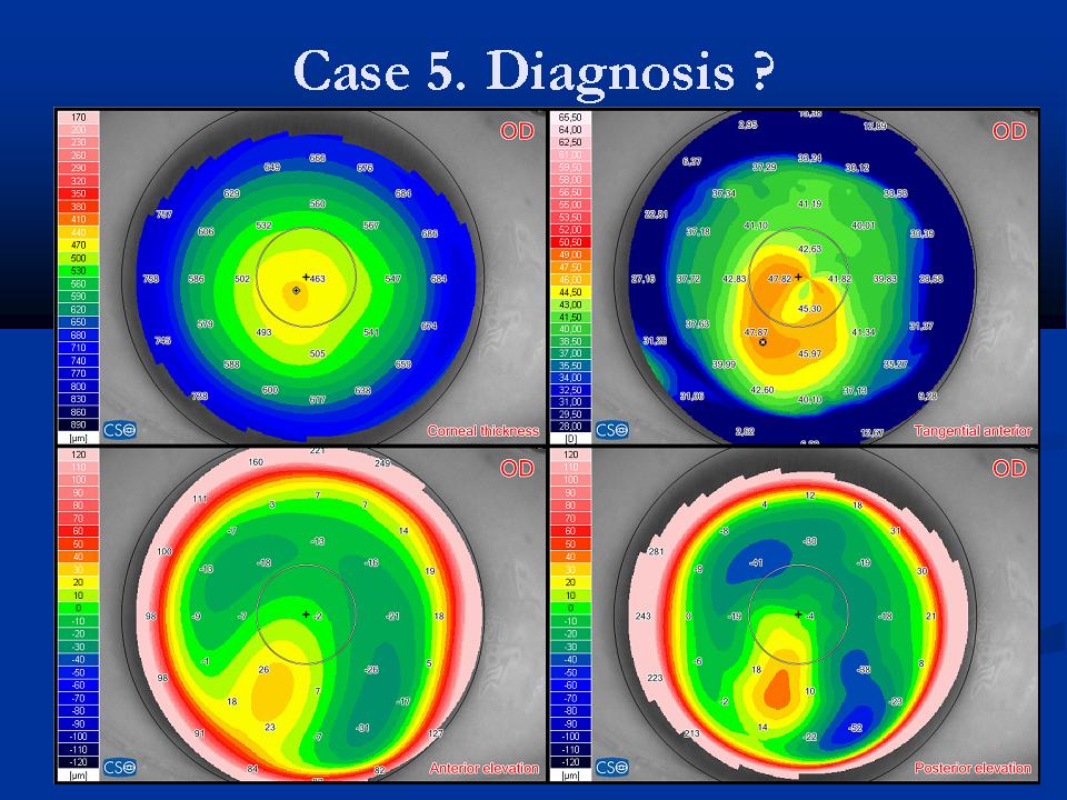
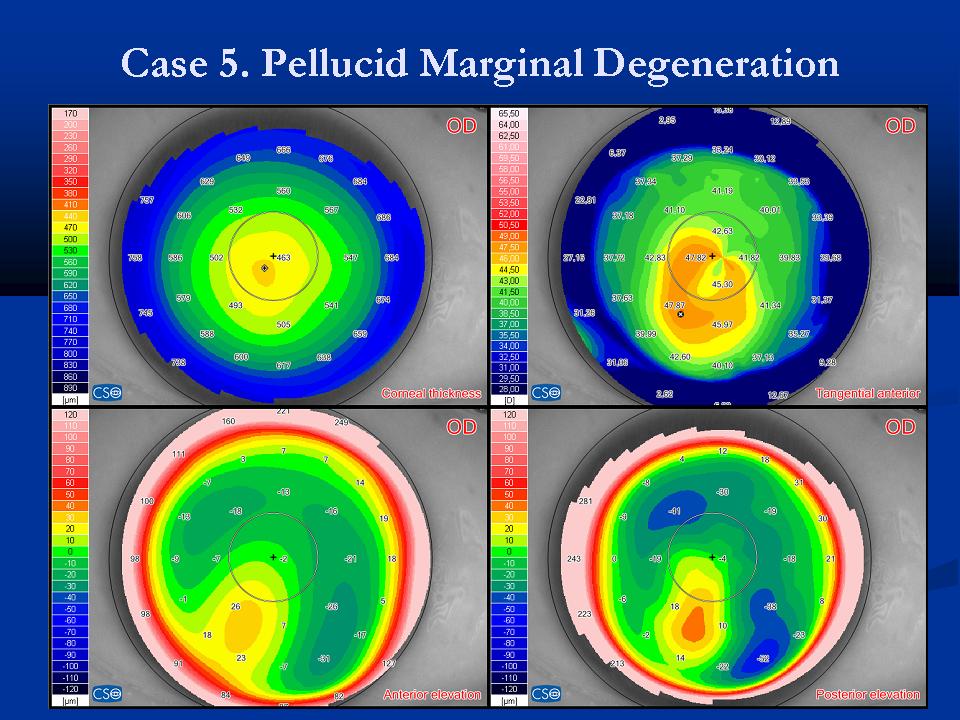
Case examples
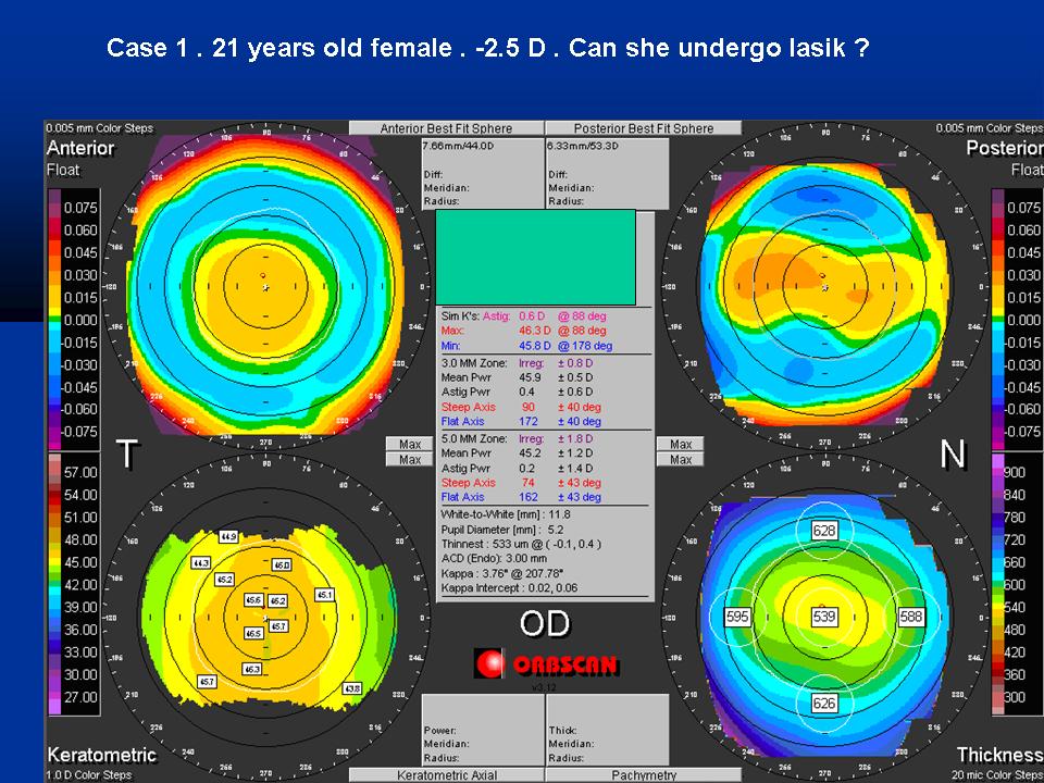
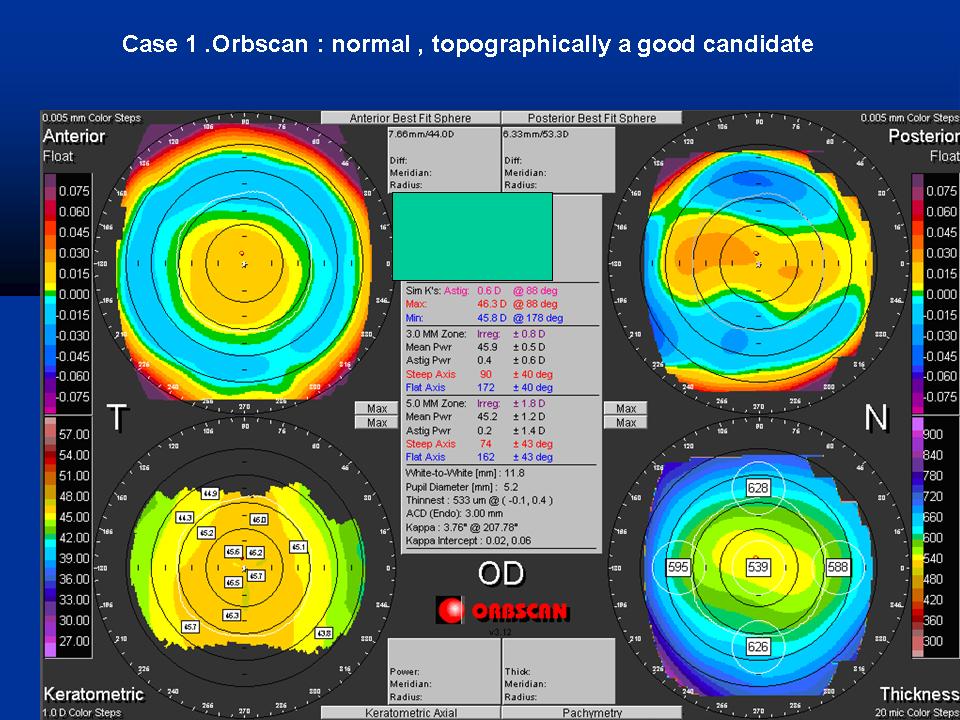
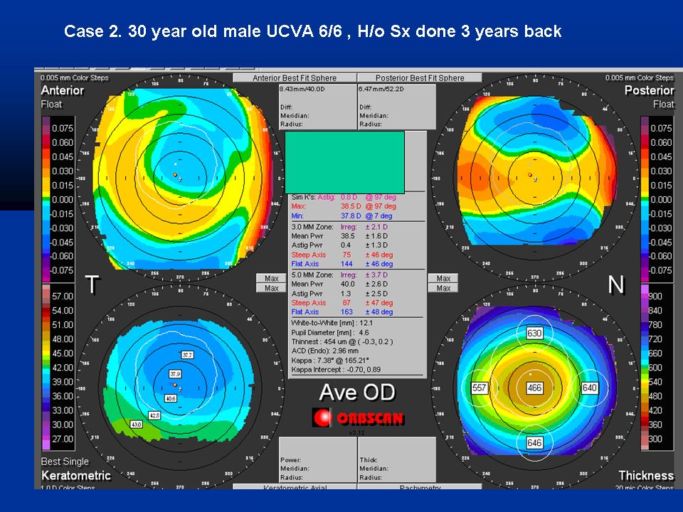
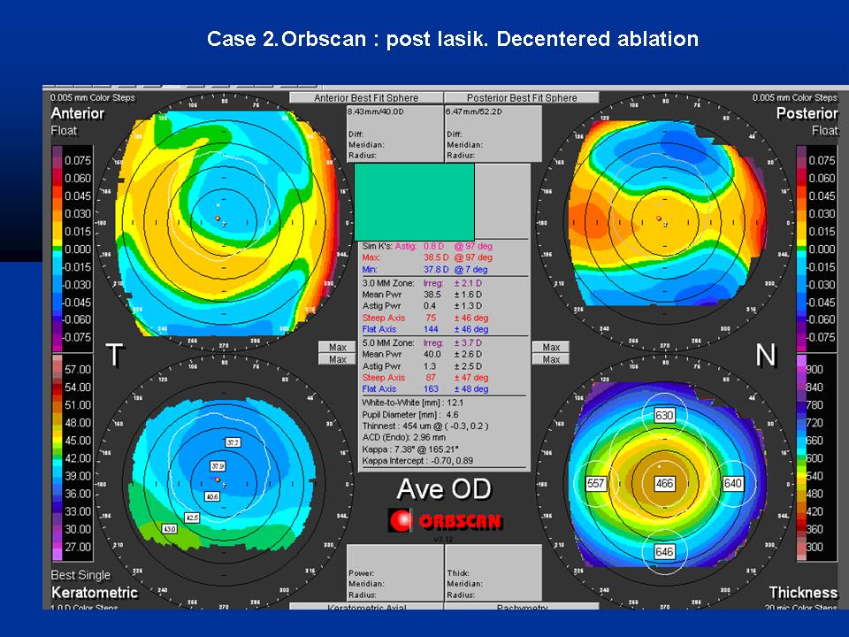
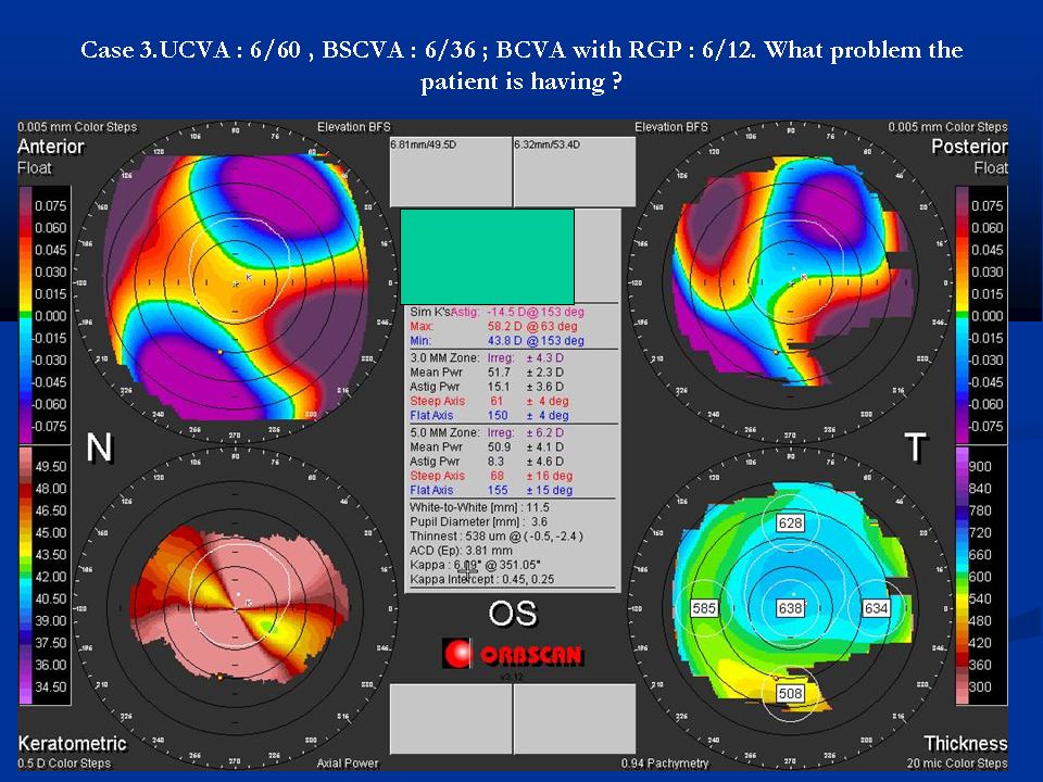
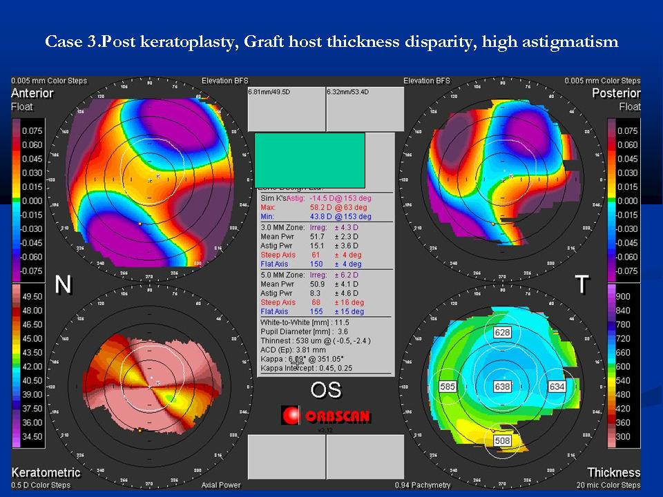
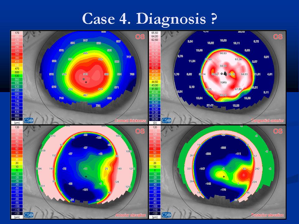
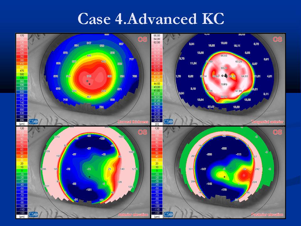 \
\ 
.JPG)
.JPG)
.JPG)
.JPG)
.JPG)
.JPG)
.JPG)
.JPG)
.JPG)
.JPG)
References
- ↑ Jump up to: 1.0 1.1 Gatinel D., Corneal Topography and Wave Front Analysis :In Albert & Jakobiec's Principles & Practice of Ophthalmology (Chapter 70, Section History of corneal topography) Retrived from http://www.expertconsultbook.com/expertconsult/ob/book.do?method=display&eid=4-u1.0-B978-1-4160-0016-7..50073-4--cesec3&isbn=9781416000167&decorator=none&type=bookPage#lpState=open&lpTab=contentsTab&content=4-u1.0-B978-1-4160-0016-7..50073-4--cesec3%3Bfrom%3Dtoc%3Btype%3DbookPage%3Bisbn%3D978-1-4160-0016-7&search=none , accessed on 22.03.2014
- ↑ Placido A: Novo instrumento per analyse immediate das irregularitades de curvatura da cornea. Periodico Oftalmol Practica 1880; 6:44-49.
- ↑ Swartz T, Marten L, Wang M. Measuring the cornea: the latest developments in corneal topography. Curr Opin Ophthalmol. 2007 ;18(4):325-33.
- ↑ Oliveira CM, Ribeiro C, Franco S. Corneal imaging with slit-scanning and Scheimpflug imaging techniques. Clin Exp Optom. 2011;94(1):33-42.
- ↑ Piñero DP, Nieto JC, Lopez-Miguel A. Characterization of corneal structure in keratoconus. J Cataract Refract Surg. 2012 ;38(12):2167-83.
- ↑ Wegener A, Laser-Junga H. Photography of the anterior eye segment according to Scheimpflug's principle: options and limitations - a review. Clin Experiment
Ophthalmol. 2009;37(1):144-54. - ↑ Jump up to: 7.0 7.1 Merklinger HM. The Scheimpflug Principle—Part I . Accessed online from http://www.trenholm.org/hmmerk/SHBG05.pdf . Accessed on 22.03.14
- ↑ [multiple authors] .Scheimpflug principle. Accessed online from http://en.wikipedia.org/wiki/Scheimpflug_principle . Accessed on 22.03.14