Optic Nerve and Retinal Nerve Fiber Imaging
All content on Eyewiki is protected by copyright law and the Terms of Service. This content may not be reproduced, copied, or put into any artificial intelligence program, including large language and generative AI models, without permission from the Academy.
Summary
Since the mid-19th century, it has been recognized that changes in the optic nerve appearance correlate with vision and visual field loss in glaucoma. Although there have been variations in the definition of glaucoma over time, increased attention to the structure and appearance of the optic nerve has been a hallmark in understanding glaucoma. Direct observation with notation progressed to accurate photographic techniques. Recently, techniques utilizing sophisticated laser scanning with digital image processing have been used to assist clinical evaluation of the optic nerve and the retinal nerve fiber layer (RNFL). This article will discuss information on evaluation of the intra-bulbar structure of the optic nerve as it relates to glaucoma, with particular emphasis on three imaging devices, confocal scanning laser ophthalmoscopy, optical coherence tomography, and scanning laser polarimetry.
Optic Nerve Anatomy
The optic nerve (optic disc, optic disk, optic nerve head [ONH]) area is approximately 2.1-2.8 mm2 in whites who are not highly myopic depending on the measurement method utilized. The optic nerve size changes in early life and is likely stable after age 10. There are significant variations in optic nerve structural parameters in homogenous populations as well as with refractive error and race.[1]
Optic Nerve in the Detection of Glaucoma
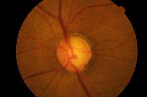
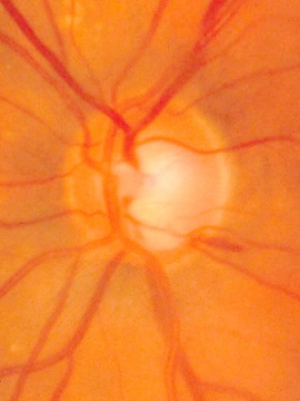
Changes in the optic nerve in glaucoma are classically considered to be cupping and pallor of the disc. The term pallor is likely to be misinterpreted to mean generalized pallor of the optic nerve. The pallor of glaucomatous optic nerves relates to the increased visibility of the lamina cribosa as compared to the neuroretinal rim (containing the ganglion cells). As the rim thins from ganglion cell loss, the cup becomes larger and often deeper exposing the lamina with increased pallor of the cup. Pallor of the neuroretinal rim indicates previous insufficiency of the vascular supply of the optic nerve which is often unrelated to glaucoma.
The retinal ganglion cells coursing into the optic nerve are responsible for the appearance of the neuroretinal rim.
The decrease in vision from glaucoma is related to the loss of retinal ganglion cells. Elevated intraocular pressure is the greatest risk factor for development of ganglion cell loss. However there appear to be a number of different pathophysiologic mechanisms by which ganglion cell loss may occur. The optic nerve appearance often provides evidence of the presence and progression of glaucoma.
| Clinical Signs of Glaucomatous Optic Neuropathy
|
|---|
| Generalized |
| Large optic cup Asymmetry of the cups (usually > 0.2)
|
| Focal |
| Vertical elongation of the cup Regional thinning Cupping to the rim margin (notching) Splinter hemorrhage Nerve fiber layer loss
|
| Less specific |
| Exposed lamina cribrosa Nasal displacement of vessels Baring of the circumlinear vessels Peripapillary atrophy |
Optic Nerve Imaging Technologies
Although other technologies exist for the evaluation of the optic nerve and nerve fiber, the following are the major technologies with the greatest installed user base in 2015.
- Disc Photography
- Confocal Scanning Laser Ophthalmoscopy
- Scanning Laser Polarimetry
- Optical Coherence Tomography
Photography of the Optic Nerve
Fundus photography has been the primary method of documenting the optic nerve until the advent of computerized imaging techniques. Fundus photography was developed in the 1920’s. The standard optic nerve photographic technique of 35mm film and now digital photography has been used extensively since the 1960’s.
Photographic documentation of the optic nerve serves multiple purposes. Single images can be used to closely evaluate the structural relationships within the nerve. Extended examination is difficult for patients and practitioners. Thus, photography allows the practitioner to evaluate fine details of the anatomy not easily seen on examination. It is not uncommon for practitioners to identify feature such as disc hemorrhages on subsequent evaluation of a photograph. In addition, photographs allow for analysis of changes in the anatomy of the optic nerve over time.
Stereo disc photography and red-free nerve fiber layer photography are additional techniques to enhance the evaluation of the disc photograph.
Stereo disc photography has greater utility in determining size and shape of the neuroretinal rim and the depth of the cup than two-dimensional photography. Stereo disc photography can be achieved utilizing several methods. A common technique is to take two photographs of the same nerve shifting the angle of the camera slightly between exposures. The resulting photographs can then be viewed with an inexpensive stereoscope viewer or similar device [2].
Although recent advances in computerized analysis of the ONH have assisted the practitioner, these methods have not completely supplanted photographic analysis of the optic nerve. In particular, the cost of optic nerve photography is substantially lower than the newer techniques.
Advantages of Optic Disc Photography
- Similar to clinical exam; comfort and easy interpretation for some clinicians
- Full color helps to distinguish between cupping and pallor
- Better detection of disc hemorrhages
- Aids in detection of peripapillary atrophy
- Stable technology
- Less expensive compared to other imaging devices
Disadvantages of Optic Disc Photography
- Qualitative, not quantitative description
- Interobserver variability
- High quality of photographs required for accurate interpretation
- May be difficult to detect subtle changes with a photograph
- Requires special hand-held lenses for viewing and interpretation
Computed Analysis of the Optic Nerve Head and Retinal Nerve Fiber Layer
Digital evaluation of the optic nerve has progressed over the last thirty years. Various techniques for analyzing photographs have been utilized to provide objective data from photography. Techniques such as stereophotogrammetry, stereo chronometry, raster stereography were developed to analyze the ONH and/or disc photographs. Often expensive and complicated, these techiques failed to reach the level of common use. In the 1990’s, three new technologies were introduced for optic nerve imaging which garnered significant interest. These are Confocal Scanning Laser Ophthalmoscopy, Optical Coherence Tomography and Scanning Laser Polarimetry.
| QUANTITATIVE IMAGING | ||
|---|---|---|
| Principles | Clinical Parameters Measured | |
| HRT | Confocal Scanning Laser Ophthalmoscopy | Optic Disc Tomography |
| GDx | Scanning Laser Polarimetry/Birefringence | Retinal Nerve Fiber Layer Thickness |
| OCT | Interferometry | Retinal Nerve Fiber Layer Thickness |
Confocal Scanning Laser Ophthalmoscopy
Confocal Laser Ophthalmoscopy (CSLO) is the concept behind the Heidelberg Retinal Tomograph. This technique for precise microscopic imaging was patented in 1955 by Marvin Minsky, now a Professor at M.I.T.[3] Since the original patent, numerous instruments in many areas of science and engineering have utilized this technique to perform precision microscopy. Confocal microscopy offers several advantages over conventional optical microscopy, including controllable depth of field, the elimination of image degrading out-of-focus information, and the ability to collect serial optical sections from thick specimens. The key to the confocal approach is the use of spatial filtering to eliminate out-of-focus light or flare in specimens that are thicker than the plane of focus. [4]
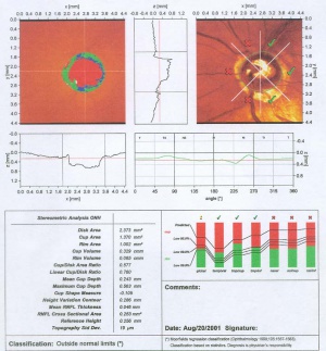
Confocal scanning laser ophthalmoscopy generates up to 64 transaxial laser scans through the ONH and peripapillary retina to reconstruct a high-resolution 3-dimensional image. A 670-nm diode laser emits a beam that is focused in the x-axis and y-axis (horizontal and vertical dimensions) of the ONH, perpendicular to the z-axis (axis along the optic nerve). The reflected image from this plane is captured as a 2-dimensional scan. Successive equidistant images are obtained, up to 64 in total, depending on the cup depth. These sections are then combined to form a 3-dimensional construct of the ONH region. Surfaces of the optic cup, optic rim, and peripapillary retina are determined by a change in reflectance intensity along the z-axis at each point. This creates a topographic map for the calculation of cup-to-disc (C/D) ratio, rim area, and other optic disc parameters. [5]
The HRT II and III instruments have become the standard instruments for CSLO scanning of the ONH in glaucoma. Description of the instrument and the concepts underlying the analysis software is available.[6][7]
Scanning Laser Polarimetry
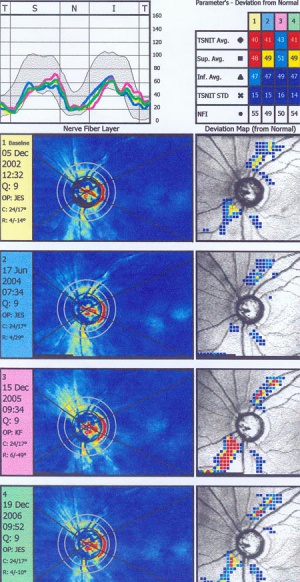
Scanning laser polarimetry (SLP) (GDx Nerve Fiber Analyzer, Carl Zeiss Meditec) measures peripapillary RNFL thickness by sending a laser beam to the posterior retina and assessing the change in polarization (retardation) of the reflected beam. This retardation of the scanning beam results from the birefringent properties of the neurotubules contained within the ganglion cell axons. The laser scanning is also based on CSLO and has a wavelength of 780 nm. A high-resolution image of 256 by 256 pixels is created of the optic nerve and peripapillary retina. Each point is a measure of the retardation of the laser scan at its location. Three serial scans are obtained with each test. Although SLP measures RNFL thickness throughout the entire image, the RNFL thickness for the double hump is determined along a 3.2-mm-diameter 8-pixel-wide circle, centered on the disc (calculation circle). The double hump is a graphic plot of the RNFL thickness around the optic nerve that is observed in most normal individuals, with the superior and inferior poles having the greatest RNFL thickness compared with the nasal and temporal poles. Some of the parameters presented are based on the RNFL thickness measurements within the calculation circle alone, but the nerve fiber indicator (a summary value that is intended to represent the likelihood of glaucomatous RNFL loss) is based on the entire RNFL thickness map. In addition, comparison of serial scans with normative data to help determine progression is available, and this is based on the entire image, not just the calculation circle. Prior versions of the machine provided a fixed compensation for the corneal birefringence that contributes to the retardation of the laser signal (fixed corneal compensation [FCC]). However, the corneal effect may differ significantly among individuals, change over time, and be substantially altered after ocular surgery, particularly LASIK. The updated device, GDx with variable corneal compensation (VCC), incorporates individualized compensation for the corneal component. [5]
Optical Coherence Tomography
Optical Coherence Tomography (OCT) is an imaging technique which utilizes the concepts of interferometry as described by Albert Abraham Michelson. The device he designed, later known as an interferometer, sent a single source of white light through a half-silvered mirror that was used to split it into two beams travelling at right angles to one another. After leaving the splitter, the beams travelled out to the ends of long arms where they were reflected back into the middle on small mirrors. They then recombined on the far side of the splitter in an eyepiece, producing a pattern of constructive and destructive interference based on the spent time to transit the arms.Most of Michelson’s work was concerning the measurement of the speed of light.[8]
The use of Optical Coherence in biological systems was described by Huang et al in 1991[9]. Since that time, instrumentation has been developed by multiple companies to utilize this technique for measurement of ophthalmic structures.
A major event in the evolution of OCT was the use of light wavelengths instead of time delay to determine the spatial location of reflected light. Through the use of Fourier transformation, this took the technology from the original method of time-domain OCT (TD-OCT) to the development of spectral-domain OCT (SD-OCT). The original OCT method, known as TD-OCT, encoded the location of each reflection in the time information relating the position of a moving reference mirror to the location of the reflection. SD-OCT, instead, acquires all information in a single axial scan through the tissue simultaneously by evaluating the frequency spectrum of the interference between the reflected light and a stationary reference mirror. This method enables much faster acquisition times, resulting in a large increase in the amount of data that can be obtained during a given scan duration using SD-OCT. A comprehensive review of SD OCT by Joel Schuman is available. [10]
OCT imaging of the RNFL, ONH, and macula has been employed as a tool to aid in the diagnosis of glaucoma. A series of devices have been manufactured to analyze each of these components. Studies have demonstrated the high analytical and diagnostic performance of OCT imaging of the RNFL, ONH, and macula for the recognition of glaucomatous and non-glaucomatous eyes.[11]
General Concepts of OCT Analysis for Glaucoma[11]
- Circular scans are centered around the ONH in order to capture RNFL and ONH measurements.
- Based on the amount of light reflected between the outer edge of the RNFL and the internal limiting membrane (ILM), the thickness of the RNFL is captured on OCT.
- With regard to the Cirrus 5000 and Spectralis devices, the thickness of the neuroretinal rim is analyzed based on the minimum rim width (MRW), which is the distance from the ILM to the Bruch membrane opening (BMO). With regard to the 3D OCT-2000, the distance between the retinal pigment epithelium and the ILM is measured.
- Macular evaluation on OCT involves analysis of the ganglion cell - internal plexiform layer (GC-IPL) thickness, as well as analysis of the ganglion cell complex (GCC) that encompasses the RNFL, GC, and IPL.
- Analysis of the macula occurs within a rectangular area that is either centered on or near the fovea.
- Thickness measurements are often shown in a TSNIT (temporal, superior, nasal, inferior, temporal) orientation and are compared to age-matched controls.
- Age-matched control analysis generally utilizes the following criteria: the Green area is the 5th-95th percentile by age, the Yellow Area is 1st-5th percentile, and the Red Area is below the 1st percentile.
| OCT Device | Analysis |
|---|---|
| Cirrus HD-OCT 5000
(Carl Zeiss Meditec, Inc., Dublin, CA) |
Parapapillary circle diameter: 3.46 mm
Data points: 40,000 RNFL analysis: o Horizontal, vertical, and circular tomograms o RNFL thickness maps o RNFL thickness plots* o TSNIT & clock-hour maps* o RNFL deviation map (for areas outside the parapapillary circle) o Table of measurements: RNFL thickness and RNFL symmetry* ONH analysis: o Table of measurements: optic nerve rim area, disc area, average and vertical C:D, and cup volume o Neuro-retinal rim thickness plots* Dimensions of analysis area—centered on fovea: 2 mm x 2.4 mm Macula analysis: o GC-IPL thickness maps o Horizontal B-scans o Sectoral plot and GC-IPL thickness table* o Deviation map |
| Spectralis
(Heidelberg Engineering, Inc., Franklin, MA) |
Parapapillary circle diameter: 3.5 mm
Data points: 760 RNFL analysis: o Infrared scout images o Tomograms o RNFL thickness plots* o TSNIT plots* o Asymmetry plot with quadrant & sectoral maps ONH analysis: o MRW analysis of 9 cross-sectional images o MRW TSNIT plots* Dimensions of analysis area—centered on fovea: 10 x 10 mm Macula analysis: o Asymmetry maps and plots for retinal thickness* |
| Avanti Widefield OCT
(Optovue, Inc., Fremont, CA) |
Parapapillary circle diameter: 4.0 mm
RNFL analysis: o Tomograms o RNFL thickness plot* o Asymmetry Plot o Table of measurements: RNFL thickness* ONH analysis: o Table of measurements: C:D (area, vertical, horizontal), disc area, rim area, and cup volume* Dimensions of analysis area—1 mm temporal to fovea: 7 x 7 mm Macula analysis: o GCC thickness maps* o Table of measurements: ganglion cell complex thickness* |
| Optical Coherence Tomography RS-3000 Advance 2(NIDEK CO., LTD., Gamagori, Japan) | Parapapillary circle diameter: 3.45 mm
RNFL analysis: o Scout images o Circumferential tomograms o RNFL thickness maps o RNFL thickness plots o Whole, superior/inferior, TSNIT, and clock-hour maps o Asymmetry plot ONH analysis: o Table of measurements: C:D (horizontal, vertical), R:D (minimum, angle), disc area, and cup area Dimensions of analysis area—centered on fovea: 9 x 9 mm Macular analysis: o Thickness maps (RNFL, GCL, and IPL combined) o Deviation maps |
| 3D OCT-2000 (TOPOCON CORPORATION, Tokyo, Japan) | Parapapillary circle diameter: 3.4 mm
RNFL analysis: o Color and red-free fundus photos o RNFL circular tomograms o RNFL thickness maps o RNFL thickness plot* o TSNIT, clock-hour, and 36-sector maps* o Symmetry analysis o Table of measurements: RNFL thickness (total, superior, inferior) ONH analysis: o Horizontal tomograms o Table of measurements: rim area, disc area, C:D (linear and vertical), and cup volume Dimensions of analysis area—centered on fovea: 7 x 7 mm Macula analysis: o GCC thickness maps o Asymmetry map o Table of measurements: GCC thickness* |
| *data compared with age-matched controlsC:D = cup to disc ratio; GCC = ganglion cell complex; GC-IPL = ganglion cell – inner plexiform layer; MRW = minimum rim width; OCT = optical coherence tomography; ONH = optic nerve head; R:D = rim to disc ratio; RNFL = retinal nerve fiber layer; TSNIT = temporal, superior, nasal, inferior, temporal | |
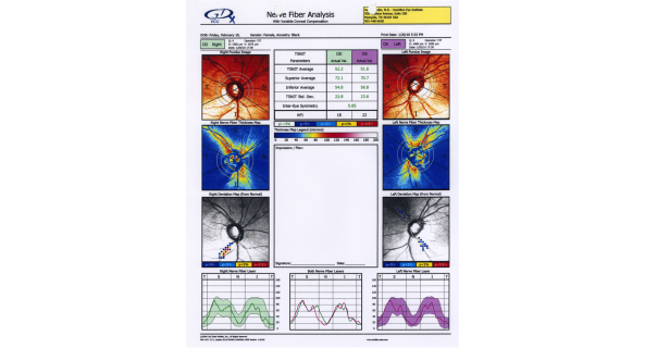
This printout reveals blunting of "double hump" appearance of RNFL in the left eye and RNFL thinning superiorly in the right eye.
Acknowledgement
Photos Courtesy of Samuel Solish, MD, EyeCare Medical Group, Portland, Maine
Conclusion
Integration of imaging modalities into the clinical evaluation for glaucoma can guide diagnostic and treatment decisions. Evaluation by OCT has shown to be particularly effective.
Additional Resources
- Medeiros, FA, Prata, JA, Tavares, IM. Optic Disc and Retinal Nerve Fiber Layer Analyzers in Glaucoma. American Academy of Ophthalmology. Current Insight 2006. https://www.aao.org/current-insight/optic-disc-retinal-nerve-fiber-layer-analyzers-in- Accessed March 25, 2019.
- Glaucoma Diagnosis, Structure and Function Reports and Consensus Statements of the 1st Global AIGS Consensus Meeting on Structure and Function in the Management of Glaucoma. Weinreb & Greve (ed) Kugler: The Hague, Netherlands 2004
References
- ↑ Jonas et al Survey of Ophthalmology 43; 4, 1999
- ↑ http://en.wikipedia.org/wiki/Stereoscopy
- ↑ http://en.wikipedia.org/wiki/Confocal_laser_scanning_microscopy
- ↑ http://www.micro.magnet.fsu.edu/primer/techniques/confocal/
- ↑ 5.0 5.1 Lin, SC, Singh, K, Jampel, HD et al Ophthalmic Technology Assessment:Optic Nerve Head and Retinal Nerve Fiber Analysis. A Report by the American Academy of Ophthalmology, Ophthalmology 2007;114;1937-1949
- ↑ Allingham, R. Rand , et al Shield’s Textbook of Glaucoma, 5th ed, Lippincott Williams & Wilkins, 2004
- ↑ http://www.agingeye.net/glaucoma/heidelberg.pdf
- ↑ http://en.wikipedia.org/wiki/Michelson-Morley experiment He won the Nobel Prize in Physics in 1907.
- ↑ Huang D, Swanson EA, Lin CP, Schuman JS, Stinson WG, Chang W, et al., Science 1991; 254:1178-81
- ↑ Joel S. Schuman, MD, Spectral Domain Optical Coherence Tomography For Glaucoma (An AOS Thesis) Trans Am Ophthalmol Soc 2008;106:426-458
- ↑ 11.0 11.1 Aref A, Rosdahl J. Focal Points 2019 Module: Optical Coherence Tomography in Glaucoma Diagnosis. In: Eric P. Purdy M, ed. Vol XXXVII. San Francisco, CA: American Academy of Ophthalmology; 2019.


