Lensometry
All content on Eyewiki is protected by copyright law and the Terms of Service. This content may not be reproduced, copied, or put into any artificial intelligence program, including large language and generative AI models, without permission from the Academy.
A review of lensometer, including its history, types of lensometers and lenses, and instructions on how to use a lensometer.
Introduction
A lensometer (also known as a lensmeter, lens neutralizer, or vertometer) is an optical instrument used to measure the dioptric vertex power, optical center, cylindrical axis, and prism of a lens. The lensometer is useful for establishing and verifying a reference refractive prescription before an eye exam. The term “neutralization” refers to the process of measuring the prescription of a refractive lens. For example, if the unknown lens has a power of +4.00D, the lensometer compensates with a focal length of -4.00D, thereby neutralizing the lens.
History of Lensometry
The history of lensometry dates back to the mid 19th century. In 1848, Antoine Francois Jean Claudet, an avid photographer and artist, developed the photographometer that could measure the intensity of photogenic rays. He later introduced a self-acting focus equalizer that could produce differential movement of the two lenses of a photographic optical combination to sequentially bring solid images into focus and prevent distortion in shifting lenses of a moving picture camera.[1] In 1876, Herman Snellen introduced the phakometer, an instrument similar to an optical bench that could be used to measure the power and location of the optical center of convex lenses.[2] In 1912, Troppman introduced the first focimeter, an instrument that enabled direct reading of the dioptric values. The first patent for a projection focimeter was issued in 1922.[1] Modern lensometers are derived from these past advances.
Types of Lensometers
Several models and designs for lensometers exist. Both manual and automatic lensometers are used on a daily basis in clinical practice.[3][4]
Manual lensometers
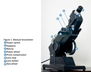
The manual lensometer is an instrument that utilizes a battery-powered, LED illumination system to measure the precise powers of the sphere, cylinder, axis, add, and prism of a lens manually. The two most common types of manual lensometer include the American Cross and European Dot.[3][4]
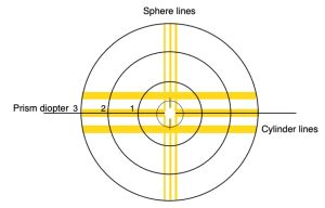
The American cross lensometer: This lensometer consists of a series of uniform lines located at right angles to one another. The lines can be rotated by 360 degrees to determine cylinder power. The triple thin lines are designated as the “sphere lines” and the single thick line is designated as the “cylinder lines”.[3][4]
The European dot lensometer: This lensometer consists of a series of uniform dots located at right angles to one another. The dots can be focused in a circular or oval pattern. A protractor grid is used to determine the cylinder axis.[3][4]
Automated lensometers
An automated lensometer is an automatic instrument that measures repeatable, fast, and reliable lens prescriptions. It is relatively less accurate but easily operatable compared to a manual lensometer. It employs a white light and ray-trace system to measure the powers of the sphere, cylinder, axis, add, and prism of a lens in a single operation. The values of each measure are then displayed digitally and can be printed or recorded manually.[3][4]
Lenses
A lensometer can neutralize various types of lenses, including single-vision, bifocal, trifocal, progressive, prismatic, and rigid gas-permeable lenses. These lenses contain four primary types of powers: spherical, cylindrical, additions for near vision, and prismatic powers.[3][4][5][6]
Single-vision lens
Single-vision lenses correct either spherical or astigmatic refractive errors. Unlike bifocal, trifocal, or progressive spectacles, they do not have additional reading power.
Multifocal lens
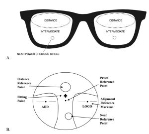
Multifocal lenses include various types of lenses, including bifocals, trifocals, and progressive lenses. They possess two or more optical powers that enhance both distance and near vision. They are frequently prescribed for correcting myopic, hyperopic, and/or astigmatic refractive, and presbyopia. The additional plus spherical power for near vision is located in the lower portion of the spectacles. Bifocal lenses incorporate both a distance and near lens. Trifocal lenses exhibit three discernible sections on the lens with correction for distance, an intermediate distance (approximately 14 inches), and near vision (Figure 4A). Progressive lenses feature intermediate and add powers that gradually increase as the wearer looks down through the lens. The gradient begins at the top portion of the glasses and reaches its maximum power at the bottom of the lens. The amount of added lens power varies from +0.50 to +3.50 diopters, depending on the amount of add required to see clearly at near. Progressive lenses have markings that indicate the manufacturer, the position of the distance power, the optical centers, and the near vision section (Figure 4B). These markings are most visible when held up to a fluorescent light.[3][4][5][6]
Prisms
Prismatic lenses shift the observed image in the horizontal, vertical, or oblique meridian. They are frequently used to aid in ocular disorders such as strabismus, nystagmus, and diplopia, and/or asthenopia. Prisms consist of both a dioptric power and a base direction. Prisms can be prescribed alone or in combination with spherical correction in a spectacle prescription. Three types of prisms can be present in glasses: incorporated, prism by decentration, and temporary Fresnel prisms. Incorporated prisms cannot be centered in the lensometer. When the lens is moved, the target will appear to jump from side to side. The higher the prismatic power, the more movement will be observed. As suggested by their name, incorporated prisms are ground into a lens. Prisms by decentration are relatively easier to be centered in the lensometer than incorporated prisms. They are apparent when the optical center of the lens is displaced in comparison to the pupillary center of the patient. These prisms are calculated using Prentice’s rule. Temporary Fresnel prisms are visible on the lens and can be removed and re-applied. They are made of plastic with visible lines.[3][4][5][6]
Rigid gas-permeable contact lens
A rigid gas-permeable lens (RGP) is a type of contact lens made from a silicone material that is smaller than conventional soft contact lenses. Unlike soft lenses, which conform to the shape of cornea, RGP lenses maintain their shape and create a tear layer between the lens and the cornea. This design allows for greater oxygen permeability compared to soft contact lenses. RGP lenses are used to correct visual abnormalities such as astigmatism and keratoconus. While they offer certain advantages over soft lenses, RGP lenses require a period of adaptation due to their rigidity.[3][4][5][6]
Techniques of Using the Lensometer
The following steps should be followed when using a manual lensometer.
Set up
- Turn on lensometer: Turn on the power switch.
- Adjust the angle of the lensometer. Position the lensometer at a comfortable angle using the lever near the back of the lensometer.
- Focusing the eyepiece. Adjust the eyepiece to compensate for examiner’s own refractive error. The following steps should be followed without a lens in place: Look into the eyepiece. Rotate the power wheel until the lines are out of focus. Turn the eyepiece in a plus direction, typically counterclockwise. Turn the eyepiece slowly in the opposite direction, typically clockwise, until the target comes into focus. If turned past this point, the measurer’s accommodation will be introduced, thus skewing the reading. Rotate the power wheel to focus the lines. The lines should come into focus at a reading of 0 on the power wheel. If this is not the case, repeat the previous steps. If distance spectacles or contact lenses are used by the examiner to focus the eyepiece, they should be worn each time the lensometer is used.[3][4][5][6]
- Positioning the lens. Place the spectacles on the moveable reticle in between the lens stop and lens holder with the temple facing away from the measurer. The bottom rims of both lenses should be placed on the lens holder and the 180˚ line should be paralleled to the reticle. While looking into the eyepiece, adjust the lens so that the lines cross in the center of the target by moving the lens on the reticle. This establishes the optical center, which can be marked with the marking pen. The addition power can be located and marked by examining the lenses under a polariscope. In general, the added spherical power for near vision in bifocal, trifocal, and progressive lenses are located on the lateral side of the spectacles.[5]
Neutralizing spherical lenses
For a spherical lens, both the thin (sphere) and thick (cylinder) lines come into focus at the same time.
- Rotate the power wheel to a high minus reading where the lines are blurry.
- Rotate the power wheel counterclockwise until the lines come into focus. The number on the power wheel indicates the spherical power.[6]
- Remember to indicate whether the reading was plus or minus. E.g., +4.00 (reads “plus four diopters), -2.00 (reads “minus two diopters).[3][4][5][6]
Neutralizing spherocylindrical lenses
If cylinder is present, sphere and cylinder lines will not come into focus at the same time. Instead, two streaks that focus at two meridians that are 90 degrees apart will be observed. Both should be neutralized separately.
American Cross lensometer
- Rotate the power wheel clockwise to a high minus reading where the lines are blurry.
- Rotate the axis wheel while simultaneously turning the power wheel counterclockwise towards the examiner to bring the thin (sphere) lines into sharp focus.
- Record the number on the power wheel, this is the spherical power. If the three thick lines come into focus first, stop and change the axis wheel by 90 degrees, this will bring the thin lines into focus.
- Leave the axis dial at its setting. Continue to turn the power wheel counterclockwise towards the examiner until the thick lines come into focus.
- Record the number on the power wheel. Cylinder power is the difference between the first and second readings.
- Record the axis indicated on the axis wheel, this is the cylinder axis. Spherocylindrical lens prescriptions are written as the following: +7.00 +1.00 x 090 (reads “plus seven, plus one at axis ninety) -1.00 - 3.00 x 180 (reads “minus one, minus three at axis one hundred and eighty)
European Dot Lensometer
- Focus one set of streaks using the steps mentioned under “measuring spherical power”.
- Focus the second set of streaks by continue to move the power wheel counterclockwise. The cylinder power will be the difference between the first and second readings.
- Using the axis marker, align the longer line with the second set of streaks that were focused. This is the cylinder axis.
Neutralizing bifocal and trifocal lenses
- Neutralize the upper portion of the lens as described under “neutralizing spherical lens” and “neutralizing spherocylindrical lenses”.
- Raise the lens until the bifocal portion is centered. Adjust the power wheel counterclockwise towards the measurer until the bifocal lines come into sharp focus. If the lens is spherocylindrical, maintain the same direction of the cylinder used to read the distance portion of the lens. The difference between the reading of the distance cylinder and the bifocal add is the power of the add. Record the add in plus power.
- For a trifocal lens, repeat the same procedure for the bifocal segment.[3][4][5][6]
Neutralizing progressive lenses
- Place the lens in lensometer so that the top, center of the lens is centered. The distance power is typically located 4mm above the pupillary center.
- Neutralize the distance power as described under “neutralizing spherical lens” and “neutralizing spherocylindrical lenses”.
- Raise the lens until the nasal inferior lens is centered. The near add is typically located 20mm below and 2mm nasal to the pupillary center.
- Neutralize the near power as described under “neutralizing bifocal and trifocal lenses”.
- If the refractive error is great than +/- 6.00D, flip the lens and read the front vertex power to determine the additive strength. The distance power is still read using the back vertex power.[4]
Neutralizing prism
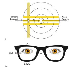
Incorporated and Fresnel prisms can be measured using three techniques: using the concentric rings inside the lensometer, using loose prisms, and using the prism compensating device.
Concentric rings
- Each line represents one prism diopter.
- The direction of the base of the prism is indicated by the direction of displacement of the target.
a. Nasally = Base in. b. Temporally = Base out. c. Superiorly = Base up. d. Inferiorly = Base down. [3][4][5][6]
Loose prisms
- If the incorporated prism is large, the optical center will be displaced beyond the scope of the lensometer rings.
- Loose prisms can be held on top of the lens in the opposite base direction to bring the optical center to neutralization. The amount of prism needed to center the target is the amount of prism in the lens.[3][4][5][6]
Prism compensating device
The prism compensating device neutralizes the prism when adjusted allowing the target to be centered.
- Place the lens against the lens stop so that the point of reference on the lens (where patient looks through glasses) is centered in the center of the lens stop.
- Set the power wheel to the sphere power of the prescription. Rotate the prism compensating device knob to bring the center of the target to coincide with the center of the reticle. This changes the prism power. Rotating this knob changes the base direction.
- The prism power and base direction are read directly from the scales. If the prism diopter scale is white, add 180° to the prism axis scale reading for base meridian.[3][4][5][6]
Prisms by decentration
Prism can be induced by decentration of the optical center of the lens.
- Prism by decentration is calculated based on Prentice’s Rule: Prism Induced = Power of lens in diopters x displacement from optical center in cm. E.g. –10.00 lens displaced 2mm temporally (shifting fixation nasally through the lens). Prism induced = 10D x 0.2cm = 2 diopters BI
- Plus lenses are two prisms base to base; minus lenses are two prisms apex to apex.
- Mark the patient’s Interpupillary distance by corneal light reflexes while wearing the glasses. The corneal light reflexes are the light reflexes within pupils.
- Place the marking in the lensometer center.
- If the position of the mires is not centered, each black ring it is off from center counts as one diopter of prism induced. (See “concentric rings”).
- The direction of the base of the prism is indicated by the direction of displacement of the target.[3][4][5][6]
Neutralizing contact lenses
- The lens stop is first replaced with a contact lens stop, which features a smaller aperture.
- The RGP lens is then placed on the contact lens stop, with the convex side facing towards the examiner.
- The power of the contact lens can be measured the same manner as that of spectacles.
- Maintain lens in its natural curvature to avoid inducing a cylindrical reading.[3][4][5][6]
References
- ↑ Jump up to: 1.0 1.1 Image. Journal of Photography of the George Eastman House. Published January 2, 1952. Accessed April 14, 2023. https://web.archive.org/web/20130312194522/http://image.eastmanhouse.org/files/GEH_1952_01_02.pdf
- ↑ Focimeters. The colleges of Optometrists. Published May 12, 2008. Accessed April 14 2023. https://web.archive.org/web/20080512081021/http://www.college-optometrists.org/index.aspx/pcms/site.college.What_We_Do.museyeum.online_exhibitions.optical_instruments.focimeter/.
- ↑ Jump up to: 3.00 3.01 3.02 3.03 3.04 3.05 3.06 3.07 3.08 3.09 3.10 3.11 3.12 3.13 3.14 3.15 3.16 Stein HA, Stein RM, Freeman MI. The Ophthalmic Assistant: A Text for Allied and Associated Ophthalmic Personnel. The Ophthalmic Assistant: A Text for Allied and Associated Ophthalmic Personnel. Published online 2006:1-896. doi:10.1097/01.opx.0000258437.13457.32
- ↑ Jump up to: 4.00 4.01 4.02 4.03 4.04 4.05 4.06 4.07 4.08 4.09 4.10 4.11 4.12 4.13 4.14 4.15 4.16 4.17 Cassin B. Fundamentals for Ophthalmic Technical Personnel. Vol 1.; 1995. doi:10.1136/bjo.82.6.715a
- ↑ Jump up to: 5.00 5.01 5.02 5.03 5.04 5.05 5.06 5.07 5.08 5.09 5.10 5.11 5.12 M.D. Wilson, Fred M., II (Editor), M.D. Blomquist PH (Editor). Practical Ophthalmology: A Manual for Beginning Residents. Vol 82.; 1998. doi:10.1136/bjo.82.4.464b
- ↑ Jump up to: 6.00 6.01 6.02 6.03 6.04 6.05 6.06 6.07 6.08 6.09 6.10 6.11 6.12 Sluser S and RG. Using the Lensometer: A Reference Guide for Ophthalmology Office. 6th ed. Tech Ophthalmology; 2008.


